Sensors & Measurement · Study deck

Sensor Circuits: Dividers and Filtering

A motor can make a sound sensor value jump even when the sensor is healthy.

Voltage Vera is your guide for this deck.

sensorcircuits
Voltage Vera, the assigned guide for sensor circuits and analogue conditioning.
iotclass.org

After studying this chapter

Learning objectives

You will be able to:

  • Design Voltage Dividers: Calculate resistor values for interfacing resistive sensors with ADCs
  • Build RC Filters: Create low-pass filters to remove noise from sensor signals
  • Implement Transistor Switches: Use transistors to control high-power loads from GPIO pins
  • Calculate LED Resistors: Properly size current-limiting resistors for LED indicators
iotclass.org

Major section

Start With the Decision

A filter reduces unwanted changes in a signal.

  • A motor can make a sound sensor value jump even when the sensor is healthy.
  • A voltage divider sets a measurable voltage from two resistances.
  • The supply provides circuit power; a pull-up resistor holds a signal line high when no device drives it low.
iotclass.org

Major section

Start With the Measurement Story

This runway does not prove every sensor or circuit is accurate.

  • The sensor may be healthy while its wiring, supply, filter, or input circuit changes the value.
  • A microcontroller means the small computer that reads inputs and controls a device.
  • A sensor signal usually reaches the microcontroller through a circuit before it becomes data.
iotclass.org

Major section

Voltage Divider Circuit
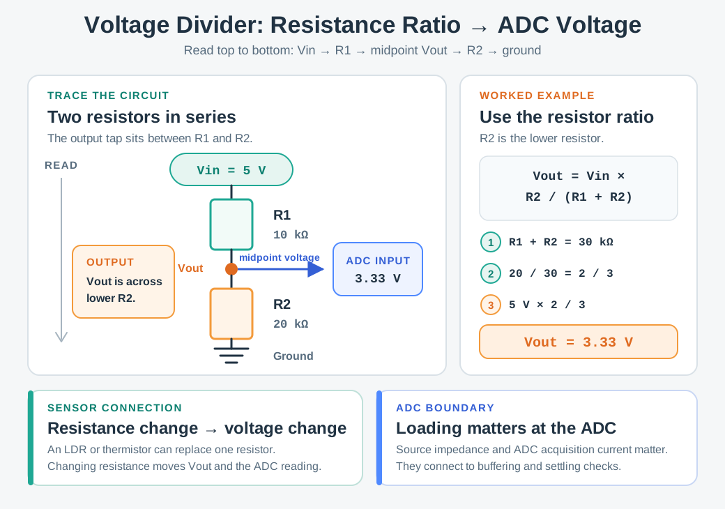
Theory: A voltage divider is the most fundamental circuit for interfacing resistive sensors (LDR, thermistors, potentiometers) with microcontrollers.

  • It converts resistance changes into voltage changes that ADCs can measure.
  • With R1 = 10 kΩ and R2 = 20 kΩ, the shown relation gives 5 V × 20/(10 + 20) = 3.33 V.
Voltage Divider: Two resistors in series create a proportional output voltage based on their ratio.
iotclass.org

Major section

Learning Points

The sensor position determines how a resistance change moves the divider output.

  • Resistive sensors change a divider ratio.
  • The output direction depends on whether the sensor is above or below the midpoint.
  • Check that the midpoint stays within the converter's input range.
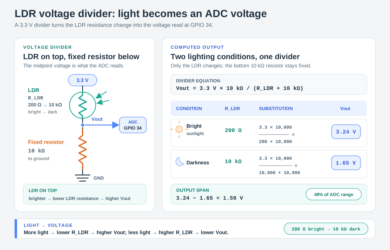
LDR Voltage Divider: Light-to-Voltage Conversion Circuit
iotclass.org

Major section

Putting Numbers to It

LDR Voltage Divider Design: An LDR varies from 200Ω (bright sunlight) to 10kΩ (darkness).

  • With the same fixed value, swapping the sensor between top and bottom reverses the direction but preserves the swing magnitude.
  • A fixed value near the geometric mean of the sensor range is a useful starting choice: 200×10,000≈1,414Ω\sqrt{200 \times 10{,}000} \approx 1{,}414\Omega200×10,000​≈1,414Ω; 1.5 kΩ is a closer standard value than 1 kΩ.
  • The worked Option 2 still uses 1 kΩ.
iotclass.org

Deck summary

Key takeaways

A useful sensor input must preserve the event while fitting the converter.

  • Divider output follows the lower-resistor fraction.
  • Check ADC range and input loading.
  • An RC filter rejects faster variation but delays wanted events.
  • Set cutoff from event speed; verify with a real step and interference.
iotclass.org

Retrieval practice

Recall check 1 of 4

Voltage Vera says: answer from memory, then check your reasoning.

Q1A GPIO pin must command a relay coil that draws more current than the pin can supply. What circuit pattern fits?

AConnect the coil to GPIO directly because the controller pin supplies enough drive for the relay.
BPut only an LED series resistor between GPIO and the relay coil.
CRead the relay coil as an ADC input instead of switching the load.
DDrive a rated transistor from GPIO; power coil separately with flyback path.
Show answer

Answer: D The pin supplies a control signal while the driver carries load current and the flyback path handles coil energy.

iotclass.org

Retrieval practice

Recall check 2 of 4

Voltage Vera says: answer from memory, then check your reasoning.

Q2A 5 V supply drives an LED with a 2 V forward drop at 20 mA. Which series resistor gives the target current?

AA 150 Ω resistor, from 3 V divided by the target 20 mA.
BA 50 Ω resistor, using only 1 V across the resistor.
CA 250 Ω resistor because the full 5 V supply appears across that resistor in this circuit.
DNo series resistor, leaving the LED current uncontrolled.
Show answer

Answer: A (5 V − 2 V) / 0.020 A = 150 Ω.

Q3A thermistor (10kohm at 25C) is placed as R1 in a voltage divider with a 10kohm fixed resistor R2 and 3.3V supply. As temperature increases and thermistor resistance drops to 5kohm, what happens to the output voltage at the junction?

ADecreases from 1.65V to 1.1V
BIncreases from 1.65V to 2.2V
CStays constant at 1.65V
DIncreases from 1.65V to 3.3V
Show answer

Answer: B Vout = 3.3V x (10k/(5k+10k)) = 2.2V. As the thermistor resistance decreases, less voltage drops across it, so output voltage increases.

iotclass.org

Retrieval practice

Recall check 3 of 4

Voltage Vera says: answer from memory, then check your reasoning.

Q4Your I2C bus has 4 sensors with 50 cm cable runs. It works at 100 kHz but fails at the required 400 kHz rate. The internal MCU pull-ups are 45 kohm. Which electrical change should be tested first?

ASwitch to SPI protocol instead of I2C
BAdd stronger external pull-ups
CReduce cable length to under 10cm
DLower the I2C clock speed to 10kHz
Show answer

Answer: B Longer cables add capacitance; measure SDA/SCL rise time and choose external pull-ups that meet the 400 kHz timing and sink-current limits.

iotclass.org

Retrieval practice

Recall check 4 of 4

Voltage Vera says: answer from memory, then check your reasoning.

Q5You need to filter 60Hz mains noise from a temperature sensor that updates every 2 seconds. What RC filter cutoff frequency should you choose?

A100 Hz, leaving 60 Hz mains noise inside the passband.
BAbout 1 Hz, below mains noise but above slow temperature drift.
C0.001 Hz, unnecessarily suppressing legitimate temperature changes.
D30 Hz, only halving 60 Hz rather than rejecting it well.
Show answer

Answer: B Correct: a 1 Hz first-order RC attenuates 60 Hz by about 35.6 dB. If readings are sampled only every 2 seconds, add adequate anti-alias filtering or sample faster and filter before decimating.

iotclass.org

Print reference

Answers 1 of 2

Answer key.

  1. D · The pin supplies a control signal while the driver carries load current and the flyback path handles coil energy.
  2. A · (5 V − 2 V) / 0.020 A = 150 Ω.
  3. B · Vout = 3.3V x (10k/(5k+10k)) = 2.2V. As the thermistor resistance decreases, less voltage drops across it, so output voltage increases.
  4. B · Longer cables add capacitance; measure SDA/SCL rise time and choose external pull-ups that meet the 400 kHz timing and sink-current limits.
iotclass.org
With the answer frame visible, compare four boundaries. A divider sets the voltage presented to the input. A driver carries relay current; the control pin does not. Pull-ups shape bus edges. A resistor-capacitor filter reduces fast variation but delays wanted events. For each circuit, compare a known input with the measured output.

Print reference

Answers 2 of 2

Answer key.

  1. B · Correct: a 1 Hz first-order RC attenuates 60 Hz by about 35.6 dB. If readings are sampled only every 2 seconds, add adequate anti-alias filtering or sample faster and filter before decimating.
iotclass.org